
Single Phase VFD: A Complete Guide to Motor Control and Phase Conversion
Marcus Chen opened a new metalworking facility in rural Oregon during the year 2024. The building only had 220V single-phase power. He had to choose between two options after purchasing a precision lathe which used a three-phase motor. He selected a VFD which operated on single phase power. His lathe system began operating effectively with existing single-phase power within one week and he obtained variable speed control as an additional advantage.
Numerous small workshops and farms and light commercial facilities throughout the world share similar experiences to Marcus. Residential and rural electrical systems use single-phase power as their primary system while industrial equipment needs three-phase motors to function properly. Engineers face difficulties because equipment needs power which is not available to them.
The guide demonstrates how a single phase VFD provides a solution to the existing problem. You will learn how these drives convert single-phase input into three-phase motor power, the critical sizing rule most buyers overlook, proper installation practices, real-world applications, and common troubleshooting fixes. By the end, you will have the knowledge to select, install, and operate a single-phase input VFD with confidence.
What Is a Single Phase VFD?
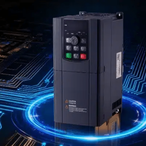
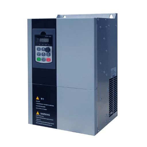
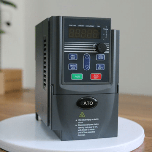
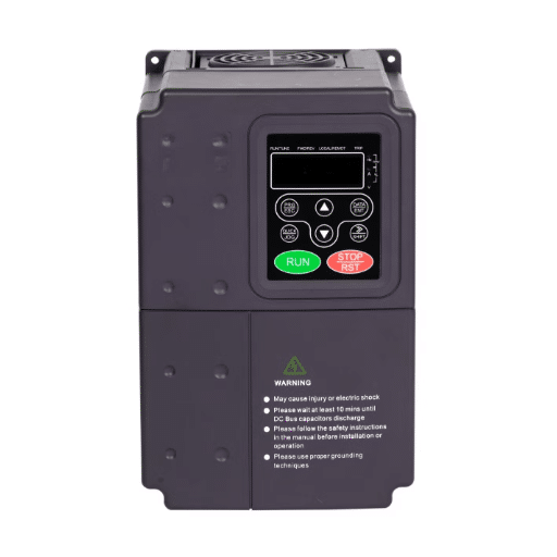
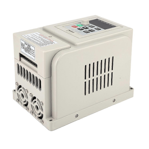
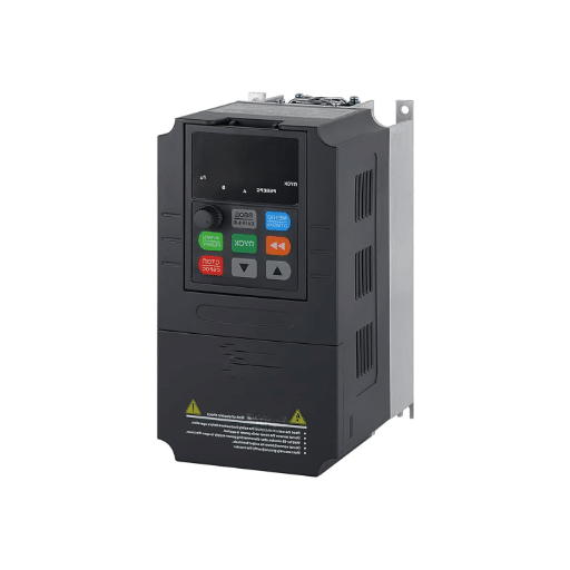
The single phase VFD operates as a variable frequency drive which accepts single-phase AC input power of 220V or 240V to produce controlled AC output for motor use. The drives exist to fulfill two separate market requirements. The industrial setup most commonly uses three-phase AC output although some models provide single-phase AC output for special functions. This system enables standard three-phase induction motors to operate effectively when only single-phase utility power is accessible.
The enclosure of the device contains three fundamental operational functions. The first function of the system involves a rectifier circuit that changes incoming AC power into DC voltage. The DC bus system uses capacitors and inductors to create smooth voltage output while minimizing voltage ripple. The inverter generates AC output through pulse-width modulation which creates output at the exact frequency and voltage required by the motor for its various operational speeds.
Shandong Electric creates single phase VFDs to address these specific applications. Our drives operate with 220V to 240V single-phase input to produce consistent three-phase output which supports motors from 0.75 kW to large industrial equipment.
Why You Can’t Use a Standard VFD on a Single-Phase Motor
Here is where many first-time buyers get confused. Customers who possess a single-phase motor already but doubt their ability to make their existing motor work with speed control. They want to know whether adding a VFD will enable them to control speed while saving energy with their current motor.
The short answer is no. Traditional single-phase motors use a centrifugal switch and a start capacitor to create the rotating magnetic field necessary for motor startup. The motor fails to achieve the reliable switching speed required by the centrifugal switch when you change the frequency through a VFD. The switch opens and closes repeatedly while the capacitor overheats and the motor experiences premature failure which can happen within a few hours.
The correct and durable approach is to replace the single-phase motor with a three-phase motor and power it through a single-phase input VFD. The device provides two functions which include phase conversion and variable speed control. The device completely removes mechanical wear from the centrifugal switch while delivering soft starting functionality which increases bearing lifespan.
In 2023, a water treatment facility in Arizona needed to upgrade a 2 HP pump system. The maintenance team attempted to maintain the existing single-phase motor while implementing a VFD for speed control on their 220V single-phase power system. The motor experienced a burnout within three days. The system operated perfectly after we installed a three-phase motor together with a properly sized single-phase input VFD. The facility manager later told us the upgrade was the best maintenance decision they had made that year.
How a Single Phase to Three Phase VFD Works
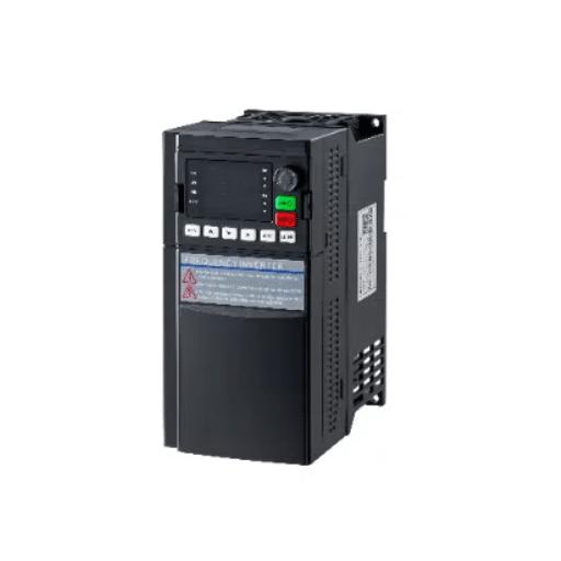
Understanding the internal process helps you make better purchasing and installation decisions. A single phase to three phase VFD works through four distinct stages, each critical to safe and efficient motor operation.
Stage 1: Rectification
The drive uses a diode bridge rectifier to convert the incoming single-phase AC into DC voltage. The current per diode in the bridge system increases because only two of the three input diodes operate with single-phase power. This is the primary technical reason that derating is necessary for single-phase input applications.
Stage 2: DC Bus Filtering
The capacitors on the DC bus system absorb the rectified voltage to decrease voltage ripple. The DC bus requires stability because any voltage changes will directly affect motor output which results in torque variations and overheating. High-quality drives use larger capacitor banks to handle the increased ripple that comes with single-phase rectification.
Stage 3: Inversion
The IGBT system uses PWM to switch DC voltage at high frequency. The drive produces three AC waveforms through its control of the switching pattern which ensures each waveform maintains a 120-degree spacing. The system generates a genuine three-phase power supply which the motor utilizes for smooth operation.
Stage 4: Motor Control
The drive’s microprocessor continuously adjusts output voltage and frequency according to the selected control mode. V/F control maintains a constant voltage-to-frequency ratio, which is ideal for general-purpose fans and pumps. Vector control provides precise torque and speed regulation, which makes it the better choice for conveyors machine tools and other demanding loads.
Sizing and Selecting a Single Phase VFD
The selection process requires its first critical step through the process of sizing. The wrong sizing choice results in three possible outcomes when the drive fails because it encounters overcurrent conditions or because it overheats or because it experiences premature failure. The VFD size requirement establishes a binding rule which requires the VFD to be sized at double the motor’s nameplate HP or kW.
The math behind this rule is straightforward. The three-phase input current distribution happens through all three rectifier diodes. The single-phase input allows only two diodes to handle the complete electrical load. The current per active diode increases by a factor of roughly the square root of 3, or about 1.73. The manufacturers establish this derating factor to protect the rectifier while achieving dependable extended operational performance.
Consider a practical example. Your 3 HP (2.2 kW) three-phase motor operates at a 220V voltage. The power ratings of a 3 HP VFD make it an appealing choice but you should avoid this option because the power ratings match your needs. The drive that meets your needs operates as a 5 HP (4 kW) product when you use single-phase input. This design provides sufficient current capacity to avoid tripping while it maintains the manufacturer’s warranty protection.
Voltage compatibility matters just as much as power rating. There are three common configurations to choose from:
- 220V single-phase input / 220V three-phase output: Use this when your motor is rated for 220V or 230V three-phase.
- 220V single-phase input / 380V three-phase output: Required if your motor is rated for 380V or 400V three-phase. These step-up VFDs include an internal voltage booster.
- 110V single-phase input / 220V three-phase output: Common for smaller motors in regions with 110V residential power, such as North America and Japan.
Never attempt to run a 380V motor on a 220V output. The undervoltage will cause the motor to draw excessive current, overheat, and eventually burn out the windings.
We also strongly recommend installing a 5% line reactor on the input side. This simple addition reduces inrush current, protects the rectifier diodes, and improves the input power factor. KEB America provides excellent guidance on line reactor selection for single-phase VFD installations.
If you are unsure which voltage class or power rating fits your motor, browse our full range of motor control solutions to compare specifications.
Installation Best Practices
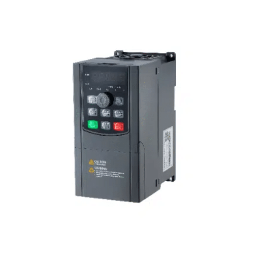
Proper installation separates a reliable system from a troublesome one. Follow these guidelines for safe, stable, and long-lasting operation.
Input Wiring
Connect the single-phase supply to the R and S terminals on the VFD input. The T terminal should remain unconnected. The T terminal should not be connected to R or S through a jumper except when the installation manual from the manufacturer provides explicit permission to do so because it will result in a phase imbalance fault.
Output Wiring
Connect the motor leads to the U, V, and W output terminals. Ensure the motor is internally wired for the correct voltage, delta or wye, according to the motor nameplate. A mismatch here will cause immediate overcurrent or under-voltage problems.
Line Reactor Placement
Install the input line reactor between the power disconnect and the VFD input terminals. Size it for 5% impedance at the drive’s rated input current. The reactor should be mounted close to the drive but with adequate ventilation clearance.
Cooling and Enclosure
Single-phase input VFDs operate at higher internal temperatures compared to three-phase VFDs because they draw more input current. The drive requires a minimum of 100 mm space above and below it to allow proper airflow. An enclosure with the required IP rating should be used when the environment includes dust and moisture and corrosive vapors.
Grounding and EMC
Use a dedicated ground wire connected directly to the VFD’s ground terminal. Keep motor cables separate from control and sensor cables to minimize electromagnetic interference. For drives operating near sensitive electronics, add an output reactor or sinusoidal filter.
Minimum Speed Limitations
Three-phase motors rely on their internal fan for cooling. At very low speeds, that fan moves too little air. Do not operate the motor at less than 20% of base speed for extended periods without adding a separate forced-ventilation fan to the motor.
Applications and Industries
Single phase VFDs bridge the gap between residential power infrastructure and industrial motor performance. They are especially valuable in locations where three-phase utility service is unavailable or would cost tens of thousands of dollars to install.
Agricultural Equipment
Irrigation pumps, grain conveyors, and ventilation fans often operate in rural areas with only single-phase power. A properly sized VFD provides soft starting, which reduces water hammer in pump systems, and precise flow control, which cuts energy use during off-peak demand periods.
HVAC Systems
Rooftop units, chilled water pumps, and air handlers in smaller commercial buildings benefit significantly from variable speed control. The VFD matches fan or pump speed to actual thermal demand rather than running at full speed and throttling with dampers or valves. This alone can cut energy consumption by 20–50%.
Water and Wastewater
Small lift stations, pressure booster pumps, and filtration systems use single-phase VFDs to maintain constant pressure while reducing mechanical wear. Soft starting also reduces stress on pipes and joints, lowering long-term maintenance costs.
Machine Shops and Light Manufacturing
Workshops and small manufacturing facilities use single-phase input VFDs to run three-phase lathes, milling machines, conveyor systems, and packaging equipment. The ability to change speed during operation enables better surface finishing on machined components while a single motor system can operate multiple product sizes on a conveyor line.
Energy Savings and Cost Analysis
The single-phase VFD business case extends beyond establishing basic phase conversion because it proves that VFD technology delivers energy savings benefits together with equipment protection and operational flexibility advantages which determine business financial performance.
Energy savings from variable-torque loads which operate like fans and pumps achieve energy savings between 20% to 50% of standard energy consumption. The physics principle states that fan or pump power requirements decrease cubically as their operating speed increases. Energy consumption decreases by almost 50% when users reduce motor speed by 20%. HVAC systems and water systems experience quick returns on investment from VFD-system upgrades because of their lower operating costs.
The government provides data which verifies these statistics. U. S. Department of Energy and NREL research shows that VFD retrofitting onto variable-load motor systems results in national industrial motor-system energy reduction of approximately 8%. The 2024–2025 ABB screening campaign evaluated 10,500 industrial motor systems and discovered that their selected variable-load applications could achieve 43% energy savings. The efficient operation of motors and drives has been shown to decrease global energy consumption by up to 10% according to worldwide research.
VFD technology eliminates startup current because it represents a major expense component. A single-phase motor operating at 10 HP requires 234 amps to start because its starting current exceeds six to eight times its normal operating current. The electrical system experiences excessive stress from the inrush which results in breaker tripping and motor winding damage. The VFD enables soft starting technology which permits motor acceleration from complete stop to working speed while preventing current voltage spikes.
The upfront costs of single-phase VFD systems and rotary phase converters appear similar however the VFD system generates faster financial returns. The VFD system enables three features which include variable speed control and energy optimization and built-in motor protection whereas the rotary converter system does not provide these functions. The majority of small-shop and commercial installations achieve complete payback within 12 to 24 months through their energy savings and maintenance cost reductions.
Sarah Okonkwo operates a small HVAC contracting business which she runs in Texas. In the summer of 2024, she installed a single-phase input VFD system to replace the 5 HP rooftop unit which she operated for her customer who only had single-phase power. The client had been paying 2,800 per month for cooling during peak season. After the retrofit, the monthly bill decreased to 2,800 per month which showed the same cooling costs as before. The equipment paid for itself in 14 months, and the client now plans to upgrade three more units using the same approach.
Troubleshooting Common Issues
Even a correctly sized and installed VFD can encounter operational problems. Here is how to diagnose and resolve the most common faults quickly.
VFD Shows Output Voltage but the Motor Does Not Turn
First, verify that voltage is actually present between all three output terminal pairs: U-V, V-W, and U-W. When one pair shows zero reading or shows much lower value than other pairs the drive system has experienced output IGBT failure. Next, run the drive at no load up to 50 or 60 Hertz and observe the display. The motor will not operate so you need to check the motor bearings for seizure and measure the winding resistance with a multimeter.
Overcurrent Trip at Startup
This usually happens when the VFD is undersized or when additional loads, such as machine controls or contactor coils, are drawing current from the VFD output. A VFD should power only the motor. Wire any external controls, relays, or contactors to the VFD’s dedicated control terminals, not the motor output terminals.
Motor Runs Rough at Low Speed
Three-phase motors are not designed for extended low-speed operation without auxiliary cooling. If your application requires continuous low-speed running, add a separate constant-speed cooling fan to the motor. Also verify that the VFD parameter settings match the motor’s rated voltage, frequency, and current.
Current Fluctuation on Pump Loads
For single-phase pump applications, erratic current often indicates an incorrect control mode or pump-specific parameter setting. Switching from standard V/F control to a pump-specific V/F curve or sensorless vector control can stabilize the output current and improve system efficiency.
Conclusion
The single phase VFD functions as a permanent solution which provides electrical power during three-phase power outages. The system functions as a complete motor control solution which combines four features into a single compact system that operates at an affordable price.
The key takeaways are clear and actionable. Replace the old single-phase motor with a three-phase motor rather than attempting to control the single-phase motor directly. The VFD should be sized at double the motor’s nameplate power because of single-phase input derating. The installation requires a 5% line reactor which protects the rectifier and enhances power quality through its input connection. The system will deliver energy savings between 20% and 50% for variable-torque applications which include fans and pumps. The motor requires both proper ventilation and established speed limits for its protection.
The right single phase VFD enables three-phase equipment operation for machine shops and irrigation systems and commercial HVAC unit maintenance without incurring utility costs. The system provides users with accurate speed control together with reduced energy costs and extended equipment lifespan.